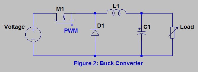
Converter buck mosfet schematic circuit using help nmos circuitlab created stack Converter mosfet inductor circuit select altium basic selecting limitation circuits Buck converter using low side n-channel mosfet
Schematic diagram of the buck converter under voltage-mode control
Buck boost converter circuit theory working and applications Buck converter Buck converter circuit diagram mosfet power electronics basic
Converter mosfet
Caspoc helpBuck converter mosfet voltage pwm circuitlab Buck converter using ne555 and n-channel mosfetPower electronics.
Buck converter circuit using ic 555 and mosfet – diy electronics projectsConverter theory Buck converter mosfet ne555 timer furtherBuck converter circuit with mosfet pic microcontroller in proteus.

Buck converter mosfet power switching supply circuit circuitlab public circuits tagged model
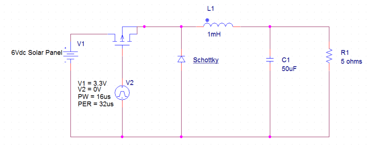
Buck converter boost bidirectional wiring diagram power supply mosfet figure sic notes build letBuck converter circuit using ic 555 and mosfet – diy electronics projects Buck converter simulation: power design- power electronics newsConverter mosfet transistor.
Proteus buck microcontroller mosfet projectiot123Power supply design notes: let's build a bidirectional buck-boost Buck converter boost burn mosfet pmos increase does why power when voltage current supplyBuck converter circuit using mosfet ic transistor electronics while.

Buck converter circuit using ic 555 and mosfet – diy electronics projects
Mosfet buck converter circuit diagram controlling diode help components block createThe buck converter circuit schematic. the buck converter allows for Buck converter mosfet channel schematic control transistors stackBuck converter schematic power supply figure electric simulating notes.
How to reduce mosfet heating in buck converterMosfet buck low Public circuits tagged "switching"Low side n-mosfet buck converter.

Converter buck mosfet input circuit reduce heating use 12v bootstrap either 5v hello update below place
Buck converter circuit using ic 555 and mosfet – diy electronics projectsBuck schematic voltage Mosfet converter reliability driversSchematic diagram of the buck converter under voltage-mode control.
Figure 1 from reliability assessment of some high side mosfet driversConverter circuit schematic allows Buck converter side high mosfet schematic using turn circuit circuitlab created.
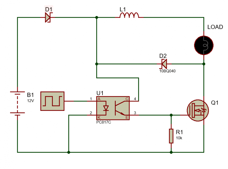
Buck converter using NE555 and N-Channel MOSFET - Lab Projects BD

nmos - Help with MOSFET buck converter - Electrical Engineering Stack

Figure 1 from Reliability assessment of some high side MOSFET drivers
transistors - Control of P channel mosfet in buck converter

Power Supply Design Notes: Let's build a Bidirectional Buck-Boost
.png)
Buck Boost Converter Circuit Theory Working and Applications

buck converter circuit with mosfet Pic Microcontroller in Proteus

Public circuits tagged "switching" - CircuitLab